BiStable
A 2 wheeled self-balancing hand following and RC ROS2 robot
For my Year 1 undergarduate course we were assigned as a group to make anything related to electronics for our 2nd term end of module project. While we could have gotten away with connecting a few sensors to a MCU and gotten a high mark, we collectively decided to make something that pushed our abilities greatly and led us to making something that at the time we werent sure how to make.
We said, let’s make a 2 wheeled self balncing robot that not only utillized control algorithms to stabllise but the tuning could be done from the same bluetooth gamepad remote that controlled it. And make the whole thing based upon the ROS2 frameowrk allowing for future scalabillity and easier additional nodes to be written for the robot. And if that wasnt enough we said lets put a camera on the robot and make it “hand following”. If the robot sees a hand in frame, it will begin following the hand mantaining a set distance apart.
This project was made start to finish in around 2 weeks so for the time constraints of the project, we were all very happy with what was achieved
Anyway lets get into what the robot was composed of and technical challenges faced

The Robots Hardware
The Robot included the following components:
- Raspberry Pi 4 8GB
- ESP32 WROOM32 dev board
- 2 x NEMA17 steppter motors
- 2x DRV8825
- 0.96 inch OLED Display
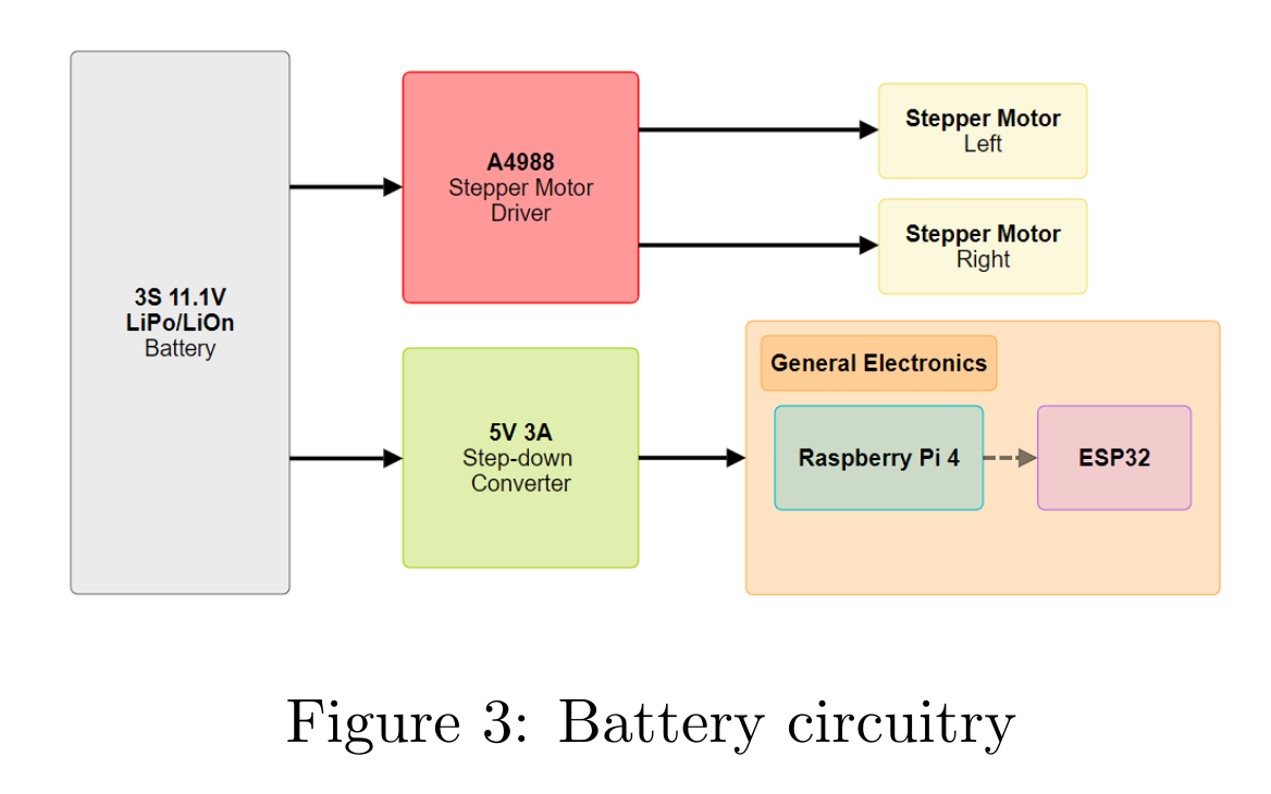
- 5V 5A step down converter
- 3S LiPo battery
- External EEPROM chip
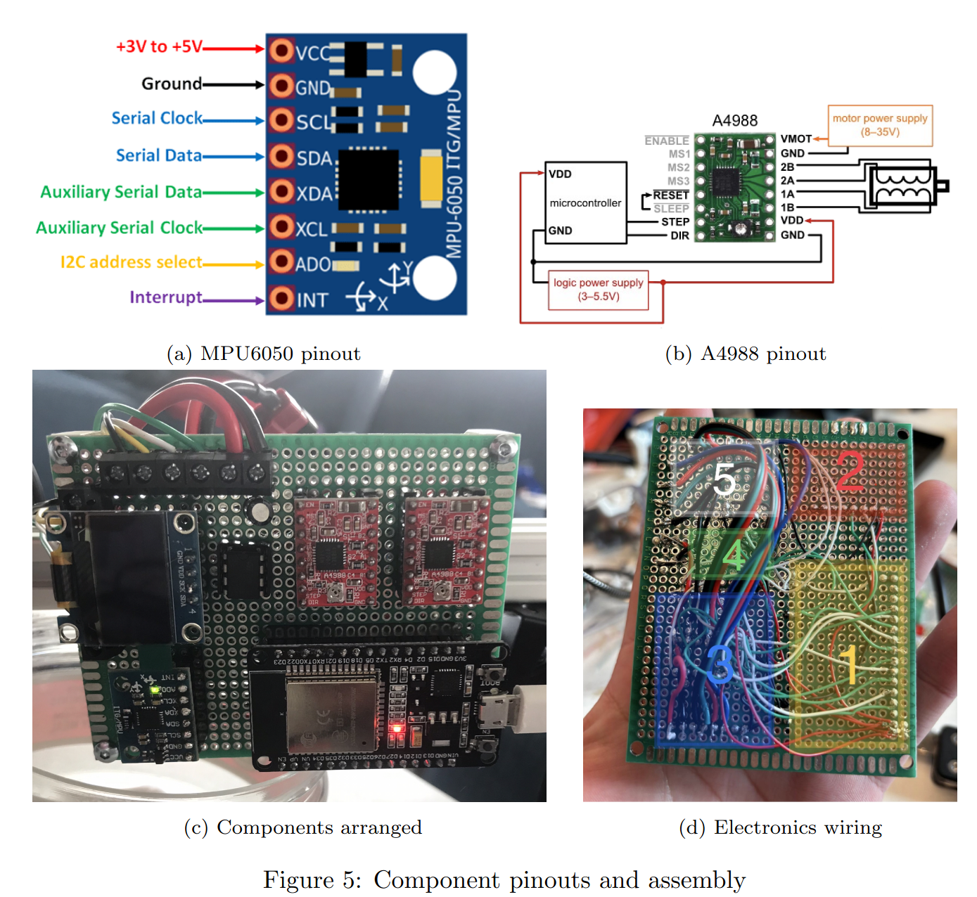
- MPU6050 6-axis IMU
- 2020 aluminium extrustion
- RGB USB camera
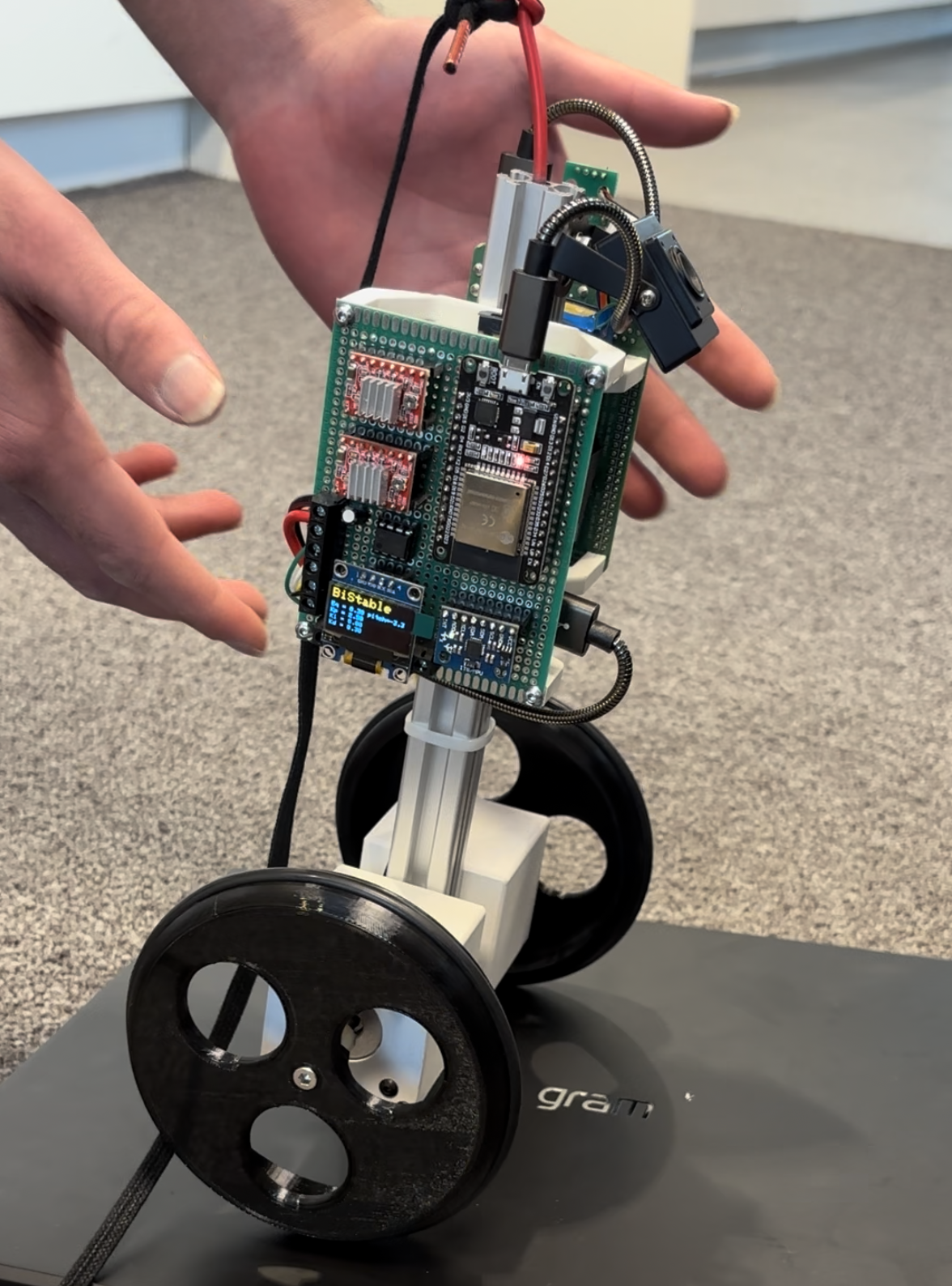
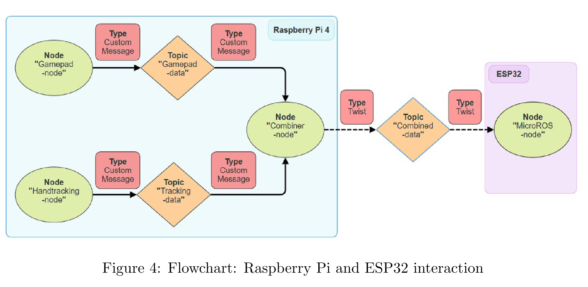
The Raspberry Pi was responsible for running ROS2, connecting to the gamepad and camera, sending custom messages to the esp32 to tell it what inclination it should be at and what its rotational velocity should be and finally what the PID gains are. More on this later
The ESP32 was the MCU responsible for stabillising the robot by reading data from the MPU6050, driving the stepper motors and writing to EEPROM
The stepper motors were used as it has high accuracy and precision while being sensorless however velocity control was found challenging while trying to execute code in the same loop. For more info fo to the section called main problems faced
Aside from that was the stepper drivers and basic electronic components like the MPU6050 IMU which is a popular choice for projects requiring an IMU, step down converters capable of supplying enough current and an EEPROM chip for saving the PID gains without needing to retune every time the robot is turned on. Information about the PID and robots inclination is found using the OLD display


For the spine of the robot we went with 2020 alumnium due to its abillity to easily mount and re-arrange components rapidly. This meant we could quickly begin programming the robot without worrying too much on the CAD itself or wasting time having to re-print parts
How everything worked
The ROS side

I want to start with the ROS side of things because before the MCU even knows how to stabillise, it needs to receive a message from the RPi telling it what angle it should be at and its rotational velocity
The robot has 4 packages that each serve a different purpose:
BiStable_scriptsBiStable_descriptionbistable_interfacesbistable_bringup
bistable_interfaces contains the message types for the rest of the ROS2 nodes. It contains 2 message types:
GamePadData.msg
float32 inclination
float32 yaw_vel
float32 eq_change
float32 kp_change
float32 ki_change
float32 kd_change
bool tracking_toggle
and for the hand tracking
TrackingData.msg
float32 inclination
float32 yaw_vel
BiStable_scripts is the main package that contains the nodes for the robot. It contains the following nodes:
-
gamepad_publisher- publishes the joystick values mapped from -1 to 1 for x and y
- button presses as 0’s and 1’s for each button and trigger
- Published using the built in message type
Int16MultiArray - publishes to the
/gamepad_datatopic
-
tracking_publisher- Publishes to
/tracking_data - Uses google mediapipe to calculate the area of the hands and find out the distance the hand is from the camera
- Used
linear_regressionto train and test the data set comparing hand area with actual distance - “area” is calculated by finding the mean magnitide of the length of each link
- Publishes to
-
combiner_node- subscribes to
/gamepad_dataandtracking_dataand publishes tocombined_data - The purpose of this node is to switch between hand following control and gamepad control
- subscribes to
The next package to discuss is BiStable_description. This contained the robots URDF’s which we could then open in Gazebo and RViz to visualize. These files were auto generated by the ros2urdf fusion360 plugin allowing for the urdf to be generated far more rapidly and be as accurate as can be.
We used the urdf in a PyBullet Simulation to test our PID control algorithm before implementing it in the actual robot.
Lastly bistable_bringup containe dthe launch files to run each node sequentially and run the microros nodes to communicate with the ESP32
The Use of microROS
For this project we needed a way for the raspberry pi to communicate with the ESP32 by sending ROS messages. In ROS1 there was a popular library called rosserial however this was discontinued over the rightly so better approach of microros
microROS was used as an arduino library and based on the syntax of the library found in the docs, we developed an script that subscribed to Tiwst messages published from the raspberry pi over USB data connection. The Twist message contained information about the inclination the robot should be at and its rotational velocity which the ESP32 used to calculate what velocity each stepper motor should be at
We can a microros agent node on the raspberry pi which allows for the esp32 to actually connect to the main ROS network. The script to run the microROS agent was also added to the launch files and we just had to click the EN button of our ESP32 to connect to the raspberry pi every time it was powered on.
microros is also based on freeRTOS which we ended up having to implement in our code to fix some major issues with controlling the stepper motors
The Biggest Problem Faced and the Solution
Near the final 2 days before the projects deadline we found that our stepper motors had very jerky motion whenever we tried doing any kind of velocity control. At first we thought it was a probelm in the stepper drivers so we spend time analyzing the connections and measuring the voltages but everything checked out.
I proposed we take a step back from our main code and make the simplest arduino sketch for a single stepper motors velocity control and we encountered the same problem. The code was justa for loop which incremented the step pulse for the stepper motors and a serial print. We found that getting rid of the serial print eleiminated the problem of velocity control and thats when it struck us
To control a stepper motor at a high resolution, its all about precisely giving pulses every few microseconds. any delay with the next pulse causes the jery motion to appear. SO it was evident that we could not have any delays in the same loop running the stepper motor.
But what was the solution? Because we dont have a mere serial print in our code but rather complex PID calculations, communication with ROS, driving the OLED display and reading IMU data. How could we have all of that removed from the lines of code controlling the stepper motor.
And thats when the solution came to me in the final 30 hours of the deadline. We use the ESP32’s second core and have the stepper control run in parallel. Doing so meant that the core dedicated to the stepper motor would have no interruptions and this fixed our problem entirely. We had to alter the priority of the tasks to skill work with microROS else the communication would to cease to work but after some tweaking, we got it working perfectly.
Luckily we had the esp32 for our project because with single core MCU, we might never had made it past that stage and been left witha robot with jerky motion