Furuta Pendulum
LQR control of a Furuta Pendulum in Gazebo
Furuta Pendulum Project
Mastering the Dynamics of Underactuated Systems: The Furuta Pendulum Project
Overview
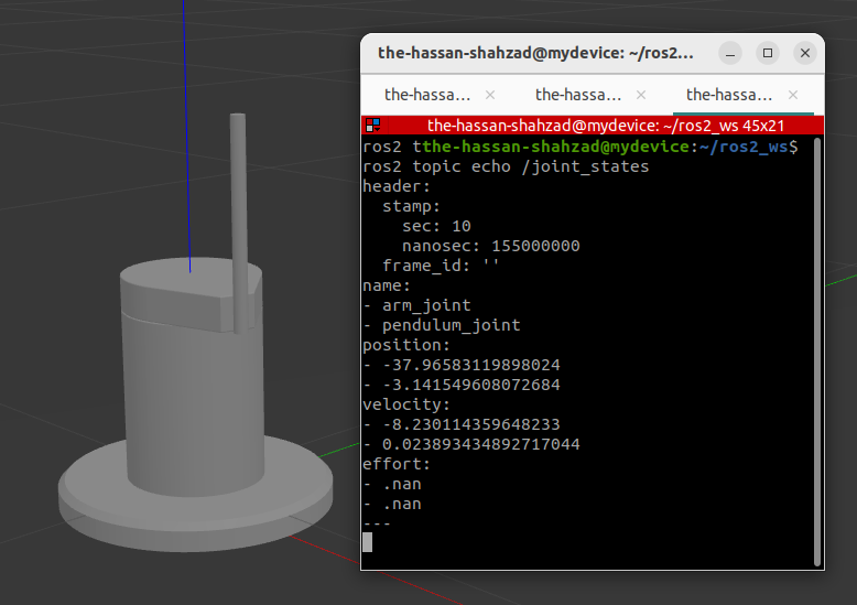
This project focuses on the mathematical modeling, system integration, and control of a Furuta Pendulum in a ROS2 + Gazebo environment. By carefully designing the physical and computational setup—ranging from deriving the system’s equations of motion to implementing an LQR controller—this project demonstrates how to stabilize an inherently unstable underactuated system. The main emphasis is on the nuances of the setup, control design, and the underlying theory rather than on the visual data plots alone.
Motivation
The Furuta Pendulum (sometimes referred to as the Rotary Inverted Pendulum) is a canonical example of an underactuated robotic system. It provides deep insight into:
- Lagrangian Mechanics for describing the nonlinear dynamics.
- Feedback Control techniques such as LQR for balancing an unstable equilibrium.
- Practical Implementation challenges in simulating and tuning underactuated systems.
Beyond being an academic benchmark, the principles learned here scale to more complex systems (e.g., robot arms, humanoids) that exhibit similar underactuated characteristics.
System Design
Mathematical Foundations
Equations of Motion
A typical Furuta Pendulum has two degrees of freedom:
- The rotary arm (actuated, angle θ).
- The pendulum rod (unactuated, angle α).
Using a Lagrangian approach, the total energy (kinetic minus potential) is computed. For instance:
- Let m be the pendulum bob mass, l be the distance from pivot to the pendulum bob center of mass, and I be the rotary arm’s moment of inertia (including motor rotor inertia).
- The angles θ (arm) and α (pendulum) define the configuration.
A simplified (yet representative) set of nonlinear equations describes how torque applied to the motor influences the system. Friction terms can be added as needed, often requiring empirical tuning.
Linearization for LQR
To design an LQR controller, the system is linearized about the upright equilibrium (arm angle 0, pendulum angle π). The state vector includes angular positions and velocities, and the control strategy balances these variables to maintain stability.
Simulation Environment
Gazebo + ROS2 Integration
- Gazebo: Provides a physics engine that simulates the rotary arm and pendulum rod using specified moments of inertia, mass, length, and friction.
- ROS2_control: Handles the hardware abstraction layer, seamlessly passing torque commands from the LQR node (or other controllers) to the Gazebo joint.
Key Steps:
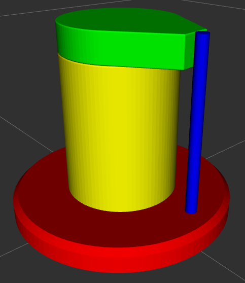
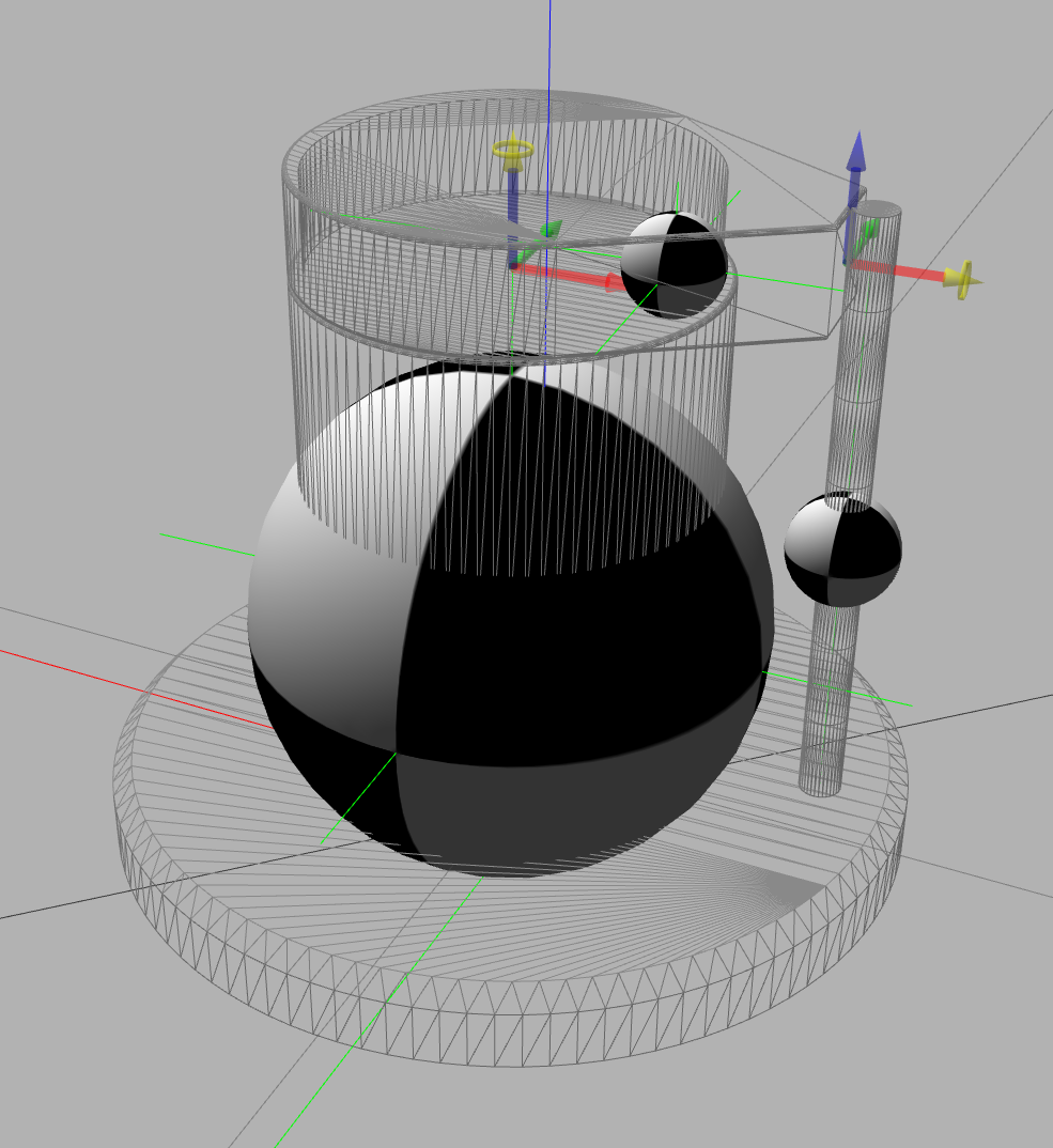
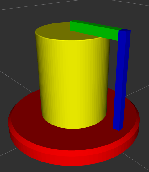
- URDF Model
- Defined links for the rotary arm and pendulum with accurate inertia tensors (mass, inertia about the respective axes).
- Specified joints, including the range of motion and friction characteristics.
- Controllers
- Joint State Broadcaster: Publishes the real-time angles θ and α.
- Effort Joint Controller: Takes in torque commands for the rotary joint.
- Additional plugins or custom nodes can handle advanced logging, sensor noise injection, or specialized debugging tasks.
- Launch Files
- Combine Gazebo environment, robot description (URDF), and controllers into a single launch script.
- Manage simulation parameters (e.g., real-time factor, friction coefficients, damping factors).
Control Objectives
- Swing-Up Control
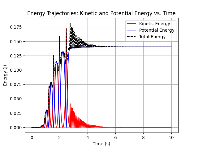
- Increase the pendulum’s total mechanical energy to reach the upright position.
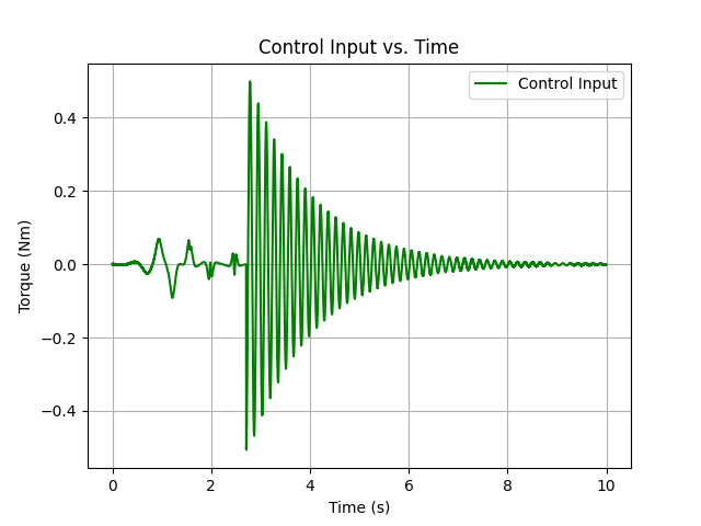
- An energy-based method was coded as a separate node that modulates torque to drive the pendulum near the upright position.
- Stabilization
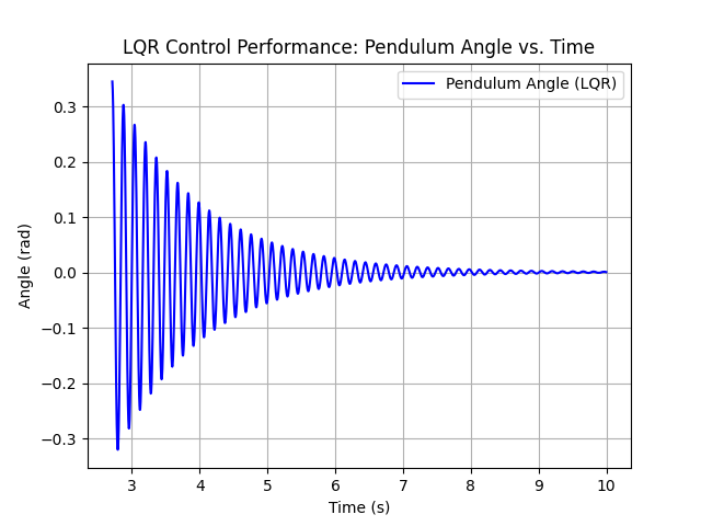
- Once near upright, switch to a Linear Quadratic Regulator (LQR).
- Minimizes deviations and achieves robust performance.
Angle Normalization
For computational convenience, angles are mapped such that the pendulum’s lowest position corresponds to 0, and the upright position corresponds to π. Modular arithmetic ensures smooth transitions and consistent state feedback.
Implementation Highlights
- Custom URDF Modeling
- Accurately defined inertial frames to reflect the real mass distribution of the pendulum and arm.
- Verified center of mass placement through both manual calculation and Gazebo’s visuals.
- ROS2 Node Architecture
-
furuta_controller_nodesubscribes to/joint_statesfor θ and α. - Implements a real-time loop to compute the required torque using either energy-based or LQR logic, then publishes commands.
-
- Code Organization
-
furuta_description: URDF, meshes, and plugin configs. -
furuta_bringup: Launch files to start Gazebo, controllers, and any auxiliary nodes. -
furuta_control: Implementation of LQR, energy-based control, and angle normalization utilities.
-
- Simulation Fidelity
- Used smaller real-time factor for debugging to “slow down” the simulation and observe transient behaviors.
- Introduced low-level friction and damping parameters in URDF to mimic real hardware.
Challenges and Insights
- Angle Offsets & Controller Handoff
- Ensuring the angles used in the LQR matched the physical reference frames.
- Smoothly blending swing-up commands with LQR commands near the upright position without torque discontinuities.
- Dynamic Tuning Loop
- The system’s sensitivity to changes in physical parameters highlighted the importance of iterative tuning for robust performance.
- Runtime Logging and Debugging
- Real-time data logging in ROS2 to track key variables and diagnose issues.
Results
- Successful Swing-Up: Smooth transitions from the lowest position to near-upright angles.
- Stabilization: The LQR controller kept the pendulum balanced with minimal oscillation.
- Robustness: Small parameter changes did not break stability, thanks to careful tuning.
Lessons and Extensions
- Hardware Realization
- Current simulation groundwork is well-suited for porting to an actual hardware Furuta Pendulum.
- Advanced Control Algorithms
- Potential to explore Model Predictive Control (MPC) or Adaptive Control for greater robustness.
- Could incorporate state observers for noisy sensor data.
- Broader Applications
- Techniques here generalize to multi-link underactuated arms, allowing deeper exploration of complex control strategies.