radioROS
A Universal Robot controller using an RC transmitter
radioROS is my solution to controlling mobile robots in simlation and in real life. Built upon the ROS2 framework, it allows for universal compatibillity with all robots ported to ROS. This was made catered to researchers and during the testing stage for robots to save time having to setup a robust controller that works over the internet when testing the robot outdoors. Alternatively the popular choice is to remote SSH into the computer and control it but with an unstable/weak WiFi proves this method to be very limited and dangerous
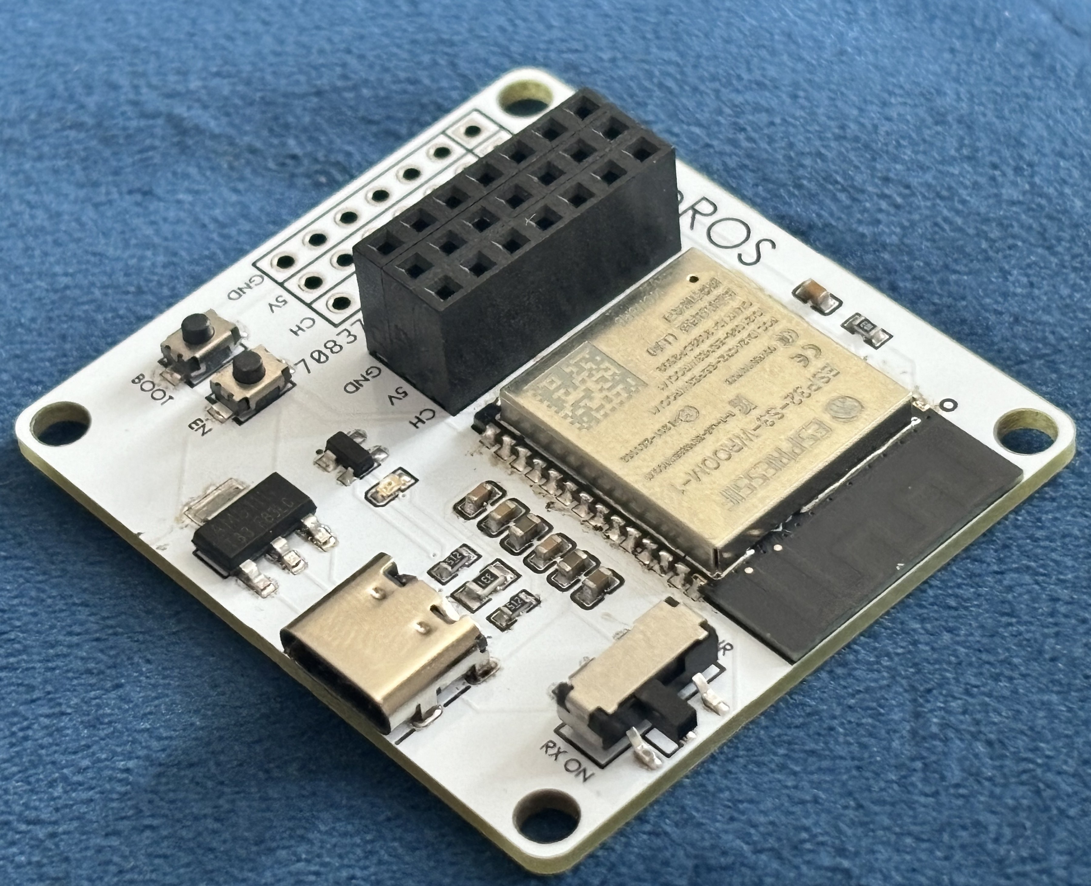
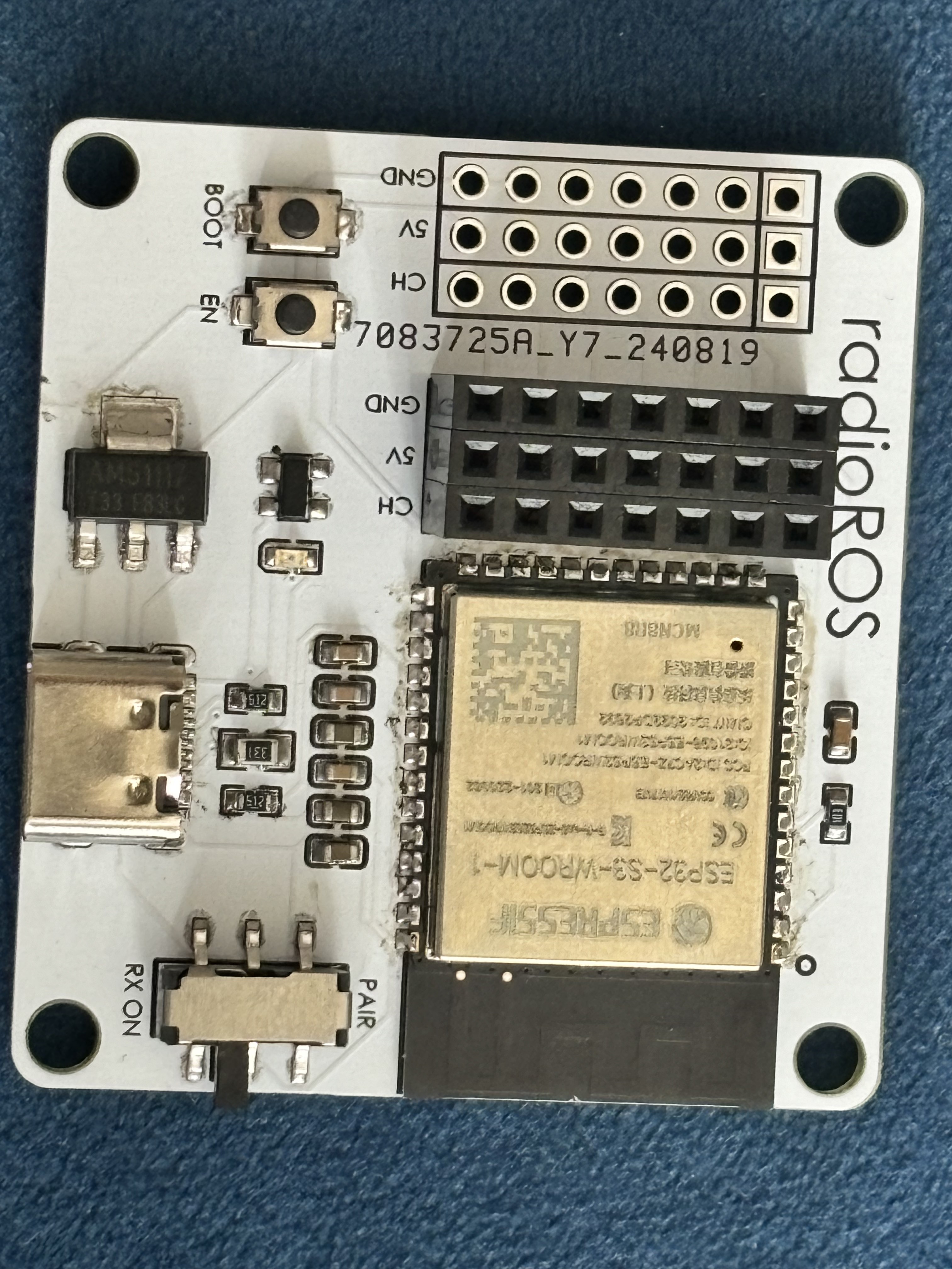
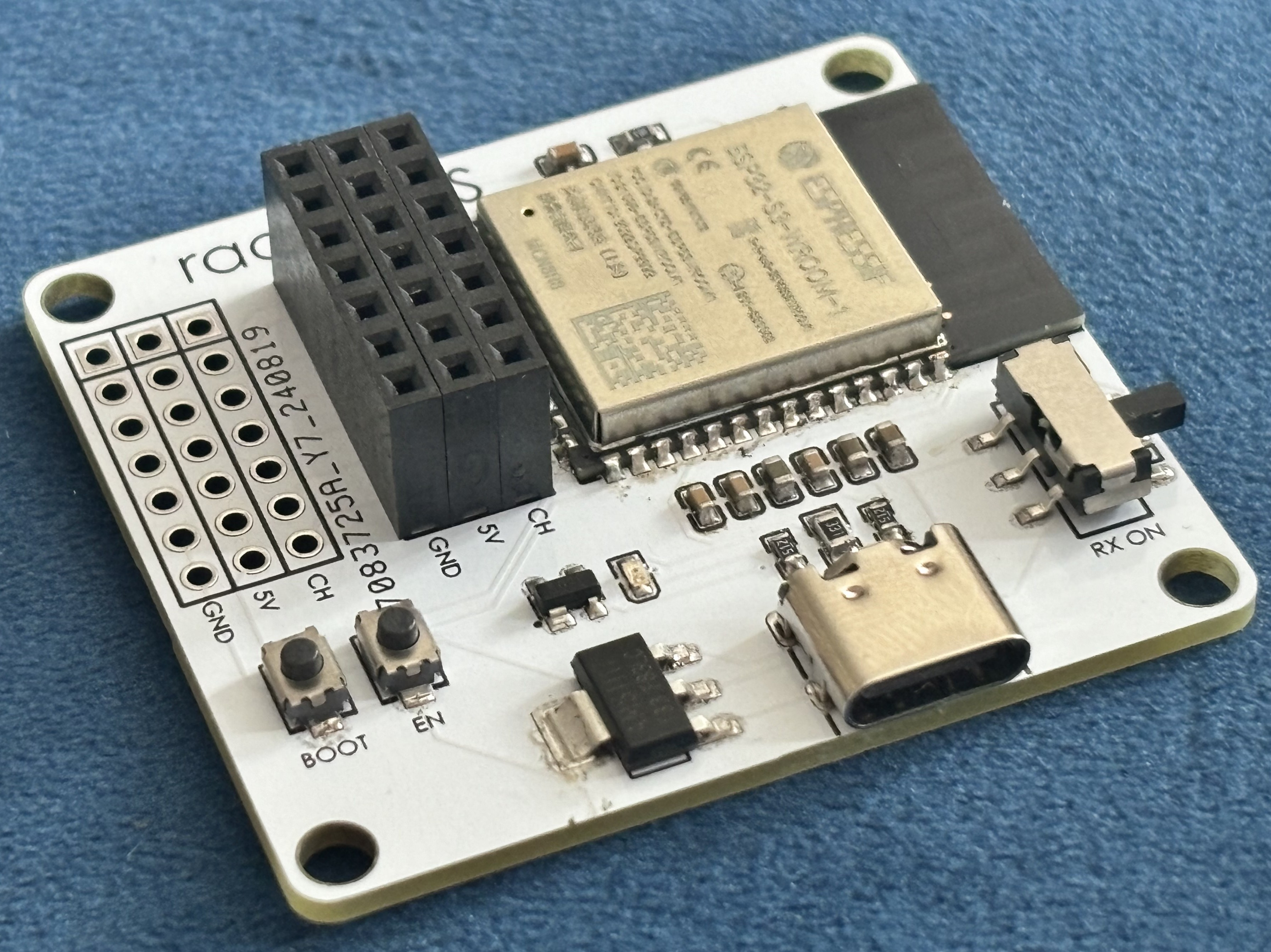
How it works
radioROS is built using an ESP32-S3 and a TGY-iA6. The ESP32-S3 has 2 notable features: it is a dual core microcontroller and it has a built in programmer. The first is crucial because the mcu uses both cores to run tasks in parallel. The first task is to read the PWM input from each receiver pin using hardware interrupts and the second task prints the data to the serial monitor every 100ms however the frequency can be increased depending on the demands of your system. Mutex is used to make sure that both cores do not try to write to the data at the same time. Lastly the data is sent using a start and stop byte to make suere the stream of data is not read incorrectly.
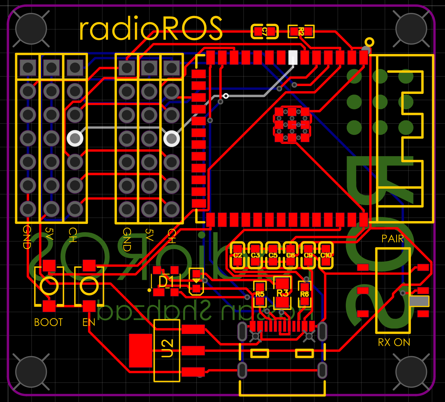
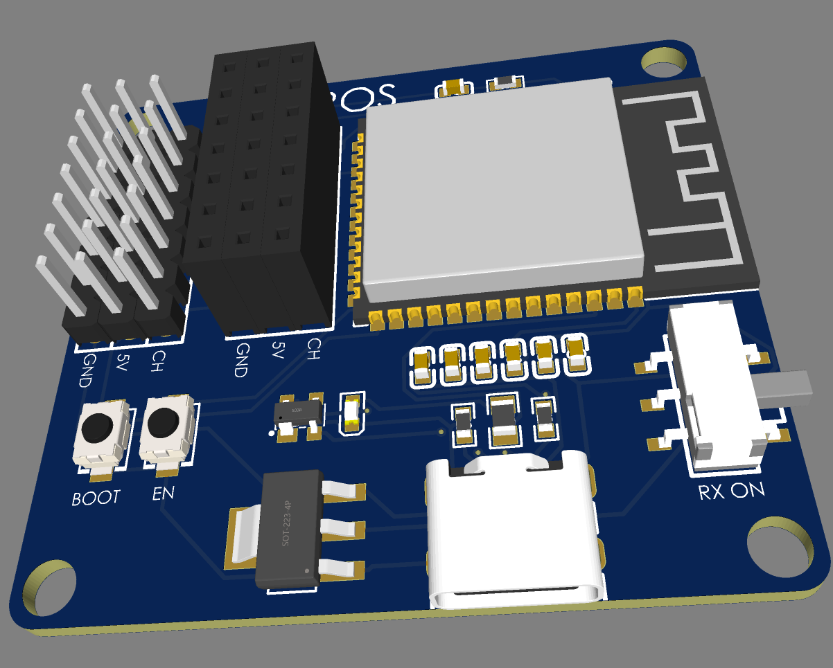
The second benefit of the ESP32-S3 is the built in programmer which reduces the need for a CP2102 USB to UART bridge. On the board theres a few components like a robust 3.3V regulator, flyback diodes to prevent corruption on the data lines, a USB type-C connector to stay with the times and external channel pins incase the receiver that the person has is not compatible with the radioROS style receiver input. Theres also a SPDT switch so that you can pair the receiver while its connected to the module and not have to unplug it, find female header pins and bind manually.
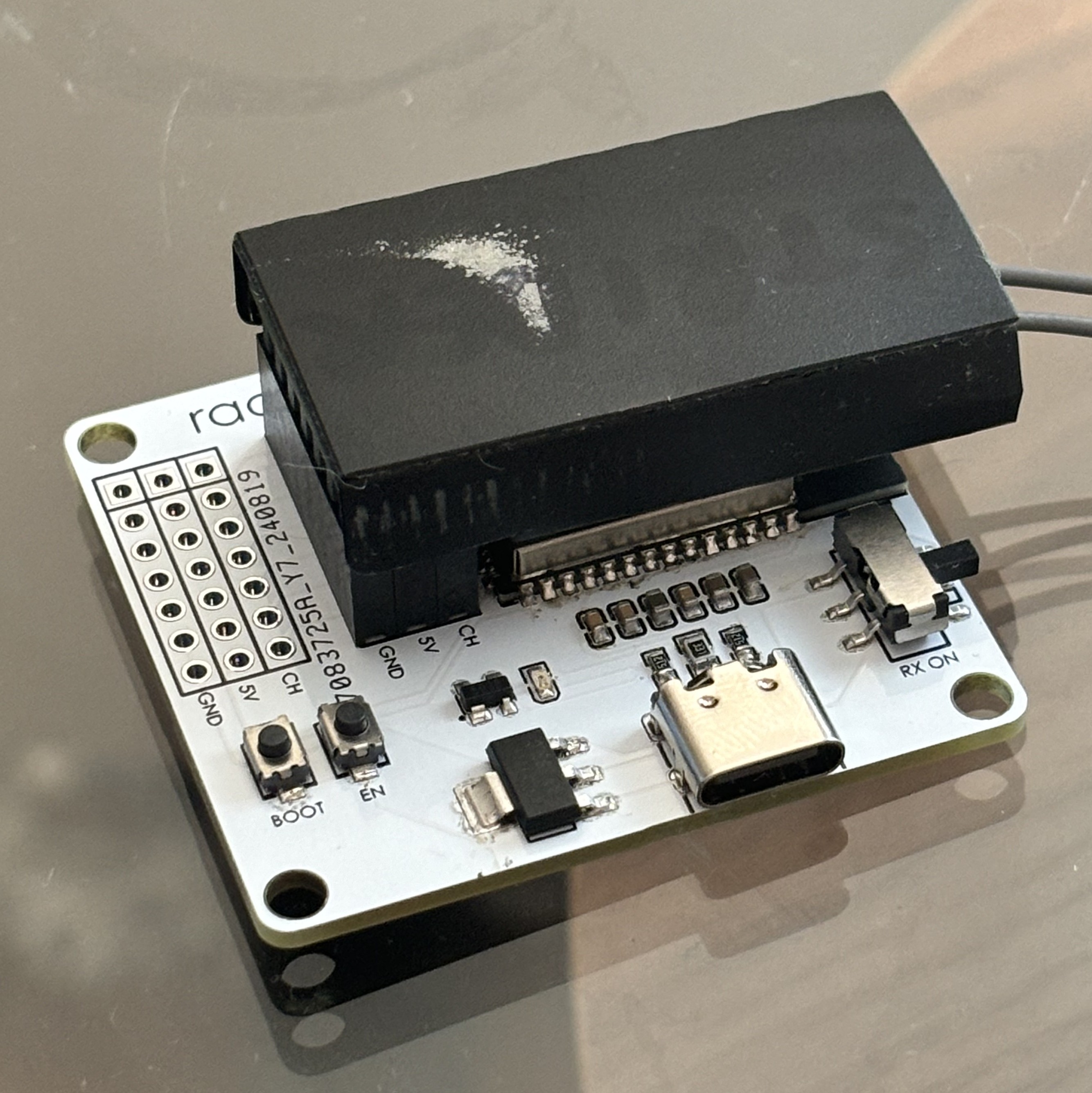
General use with ROS2
The board has a ROS2 driver package to support its use. The package currently contains 2 nodes but more can easily be added based on your use case. The first node to always run is the pwm_publisher node. Optional paramaters are serial_port and it publishes each channels pwm value from roughly 1000-2000 (depending on how your transmitter is setup) to the topic receiver_data. The default paramater for serial port is /dev/ttyUSB0 but i often find myself changing it to /dev/ttyACM0 depending on the computer. You can change the with:
ros2 run radioROS pwm_publisher --ros-args -p serial_port:=/dev/ttyACM0
The second node is pwm_to_twist which publishes a twist message based on the data received from receiver_data topic. Optional paramaters are max_linear_speed (default is 1 m/s), max_angular_speed (default is 1 rad/s) and topic (default is ‘cmd_vel’). You can change the paramaters with a command similar to:
ros2 run radioROS pwm_to_twist --ros-args -p max_linear_speed:=0.25 -p max_angular_speed:=0.02 -p topic:=/robot/cmd_vel
A Twist message is a common message type that mobile robots use to move around in the world. It consists of 2 3x1 vectors representing linear velocity along the x,y,x axis and another vector for the rotational velocity. For a simple 2 wheeled robot is only needs a linear.x and angular.z since by convention in ROS, robots face the X-axis and the Z-axis faces upwards. the rest can be set to 0. The pwm_to_twist node just takes in the receiver data and utillises channel 1 and 2 to then control a simple 2 wheeled robot.
PCB design
The PCB was designed using EasyEDA and JLCPCB to manufacture the PCB’s. The schematic was fairly easy to design and i tried using as many easily available parts as possible

Here is what the PCB rendering looks like:
SMD soldering
The soldering was done using a stencil also provided by JLCPCB and a mini hot plate. I used a 138 degree celcius solder paste and after a few tries i got it working properly. I found that you have to reduce the stencil shaking as much as possible else the solder paste will smudge leading to more manual work needing to be done to fix the solder bridges.
Placing the SMD components was also a hassle as all i have was a pair of blunt tweezers but ideally i would have a pedal assisted suction pump.
Future Improvements
Right now the board is limited to a simple 6 channel RC receiver and many receivers have totallly different layouts and numbers of channels. Ideally the board should be able to support a number of protocols like SBUS and PPM however SBUS has several drawbacks as each company like Futaba have their own propietary software. PPM is also a 1 wire communication but like SBUS not all receivers support it.
Also i would like to have a python package support and most importantly C++ drivers to make the code run far more efficiently.